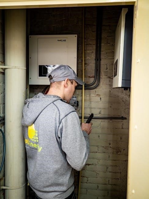
A schematic solar panel wiring diagram provides a visual guide for connecting components like panels, batteries, and inverters. It ensures safe and efficient system installation, helping users plan and troubleshoot setups effectively. Detailed PDF diagrams are widely available online, catering to various configurations and applications.
1.1 What is a Schematic Solar Panel Wiring Diagram?
A schematic solar panel wiring diagram is a visual representation of a solar panel system’s electrical connections. It uses symbols and lines to illustrate how components like solar panels, charge controllers, batteries, and inverters are interconnected. This diagram is essential for understanding the flow of electricity in the system, from the panels generating power to the final output. Unlike physical wiring diagrams, schematics focus on the logical relationships between components rather than their physical locations. They are often included in schematic solar panel wiring diagram PDF guides, providing a clear and simplified way to plan and install solar systems safely and efficiently.
These diagrams are particularly useful for installers and DIY enthusiasts to visualize the entire system before starting the installation process. They help ensure that all components are correctly connected and that the system operates as intended. By following the schematic, users can avoid common electrical mistakes and ensure a safe, functional solar panel setup.
The diagrams typically include symbols for solar panels, charge controllers, batteries, inverters, fuses, and cables. They may also show the direction of current flow, helping users understand how energy moves through the system. Whether you’re installing a small off-grid system or a large-scale solar array, a schematic wiring diagram is an indispensable tool for success.
1.2 Importance of Using a Schematic Wiring Diagram for Solar Panels
Using a schematic wiring diagram for solar panels is crucial for ensuring a safe and efficient installation. It provides a clear roadmap of the electrical connections, helping installers avoid costly mistakes. By following the diagram, users can ensure that all components are properly connected, reducing the risk of electrical hazards and system malfunctions. A schematic wiring diagram also simplifies troubleshooting, as it allows users to quickly identify and resolve issues. Additionally, it ensures compliance with electrical codes and standards, which is essential for safety and legal requirements. Whether you’re working with a small DIY setup or a large-scale solar array, a schematic diagram is an essential tool for achieving a reliable and efficient solar energy system.
Referencing a schematic solar panel wiring diagram PDF ensures that the installation aligns with best practices, minimizing errors and maximizing performance. It also helps in planning the system layout and selecting the right materials, saving time and resources. Overall, a schematic wiring diagram is a cornerstone of a successful solar panel installation, ensuring safety, efficiency, and long-term reliability.
Components of a Solar Panel Wiring System
A solar panel wiring system includes solar panels, charge controllers, batteries, inverters, fuses, circuit breakers, and busbars. These components ensure efficient energy flow and system safety, as detailed in a schematic solar panel wiring diagram PDF.

2.1 Solar Panels: Series and Parallel Configurations
Solar panels can be connected in series or parallel configurations to achieve desired voltage and current levels. In a series setup, panels are connected positive-to-negative, increasing total voltage while maintaining current. This configuration is ideal for systems requiring higher voltage, such as charging high-voltage batteries. In a parallel setup, all positive terminals are connected together, and all negative terminals are connected together, increasing current while maintaining voltage. This is suitable for applications needing higher current at the same voltage. A schematic solar panel wiring diagram PDF provides detailed visual guidance for these configurations, ensuring safe and efficient energy generation. Proper planning and wiring are crucial to optimize performance and safety in solar energy systems.
2.2 Charge Controllers and Their Role in Solar Systems
A charge controller is a critical component in solar panel systems, regulating the flow of energy from the panels to the battery. Its primary function is to prevent overcharging, which can damage the battery, and ensure efficient energy storage. Charge controllers also protect the system from overvoltage and reverse current flow. There are two main types: PWM (Pulse Width Modulation) and MPPT (Maximum Power Point Tracking). MPPT controllers are more efficient, optimizing energy harvest from the panels. A schematic solar panel wiring diagram PDF will illustrate how to connect the charge controller correctly, ensuring proper system operation. This component is essential for maintaining the health and performance of the entire solar energy system.
2.3 Deep Cycle Batteries for Energy Storage
Deep cycle batteries are designed to store excess energy generated by solar panels for later use. Unlike standard car batteries, they can handle deep discharges and replenishment repeatedly without damage. These batteries are a key component in off-grid solar systems, providing power during nighttime or cloudy days. A schematic solar panel wiring diagram PDF will detail how to connect deep cycle batteries to the system, ensuring proper energy storage and supply. They are typically rated in ampere-hours (Ah) or kilowatt-hours (kWh), and their capacity must match the system’s energy needs. Regular maintenance, such as checking electrolyte levels and terminal connections, is essential for longevity and performance. Proper installation ensures safe and reliable energy storage.
2.4 Inverters: Converting Solar Power to Usable Electricity
Inverters play a crucial role in solar panel systems by converting direct current (DC) power generated by solar panels into alternating current (AC) electricity, which is usable for household appliances and devices. A schematic solar panel wiring diagram PDF will illustrate how inverters are integrated into the system, ensuring proper connections and energy flow. Inverters also regulate voltage and frequency to match grid standards, making them essential for both off-grid and grid-tied systems. Different types, such as string inverters, microinverters, and hybrid inverters, offer varying levels of efficiency and customization. Proper installation and configuration of inverters are critical for system performance, safety, and energy optimization. They also provide overvoltage protection and monitoring capabilities to ensure reliable operation.
2.5 Fuses, Circuit Breakers, and Busbars for Safety
Fuses, circuit breakers, and busbars are essential components in a solar panel wiring system, ensuring electrical safety and reliability. A schematic solar panel wiring diagram PDF will detail how these devices are integrated to protect the system from overcurrent, short circuits, and electrical faults. Fuses act as sacrificial devices, melting to interrupt the circuit during overcurrent conditions, while circuit breakers provide resettable protection. Busbars serve as common connection points for multiple circuits, ensuring efficient energy distribution. Proper installation and sizing of these components are critical to prevent electrical hazards and ensure compliance with safety standards. They also enhance system maintainability by providing clear isolation points for troubleshooting and repairs, making them indispensable in any solar panel setup.
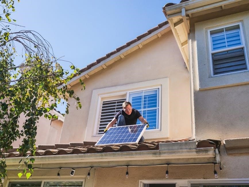
Wiring Configurations for Solar Panels
Solar panel wiring configurations include series, parallel, and hybrid setups. Series connections increase voltage, while parallel boosts current. Hybrid combines both for optimal energy output and flexibility, ensuring systems meet specific voltage and current requirements. Proper configuration is essential for efficiency, safety, and compatibility with charge controllers and inverters. A schematic solar panel wiring diagram PDF provides clear visual guidance for implementing these setups correctly. Understanding these configurations helps in designing a system that maximizes energy production based on available space and energy needs. Always refer to a reliable wiring diagram to ensure safe and efficient installation. This ensures your solar panel system operates at peak performance and meets all safety standards.
3.1 Connecting Solar Panels in Series
Connecting solar panels in series involves linking the positive terminal of one panel to the negative terminal of the next. This configuration increases the system voltage while maintaining the same current level. Series connections are ideal for applications requiring higher voltage, such as charging batteries or matching charge controller requirements. When connecting in series, ensure all panels have the same specifications to avoid imbalance. Secure connections using appropriate wire size to minimize power loss. A schematic solar panel wiring diagram PDF provides a clear visual guide for series connections, helping to ensure safety and efficiency. Always disconnect the system before making adjustments and follow safety protocols to prevent electrical hazards. Proper series wiring maximizes energy output and system performance. Use a reliable diagram to avoid errors and ensure compliance with electrical standards.
3.2 Connecting Solar Panels in Parallel
Connecting solar panels in parallel involves linking all positive terminals together and all negative terminals together. This configuration increases the system current while maintaining the same voltage level. Parallel connections are beneficial for systems requiring a lower voltage but higher current output. They also provide redundancy, as the system continues to function if one panel fails. Ensure all panels are compatible and have the same voltage rating for optimal performance. Use appropriately sized wires to minimize power loss. A schematic solar panel wiring diagram PDF offers a detailed guide for parallel connections, ensuring safe and efficient installation. Properly planned parallel wiring enhances energy output and system reliability. Regular maintenance and inspection are essential to uphold performance and safety standards. Always refer to a trusted diagram for accurate connections.
3.3 Hybrid Configurations: Combining Series and Parallel
Hybrid configurations combine series and parallel connections to optimize voltage and current output. This setup allows users to achieve a balanced system, meeting specific energy requirements. By connecting panels in series for higher voltage and then grouping these strings in parallel, the system becomes more versatile. Hybrid configurations are ideal for large-scale installations or systems with varying energy demands. A schematic solar panel wiring diagram PDF provides detailed guidance for designing such setups. This approach minimizes power loss, enhances scalability, and ensures redundancy. Proper planning and wiring are essential to maximize efficiency and safety. Hybrid systems are highly flexible, accommodating different panel configurations and energy storage needs. Always follow a trusted diagram for accurate implementation. Regular monitoring ensures optimal performance.

Safety Considerations in Solar Panel Wiring
Ensure proper insulation, grounding, and use of protective devices like fuses and circuit breakers. Adhere to local electrical codes to prevent hazards and maintain system integrity safely. Always follow a trusted schematic solar panel wiring diagram PDF for secure connections and compliance. Regular inspections are crucial to identify potential risks. Proper safety measures protect both the system and users from electrical shocks or fires. Secure all connections to avoid loose wires, which can cause arcing or short circuits. Grounding ensures safe current flow during faults. Use appropriate ratings for wires and components to handle the system’s power output efficiently. Safety should never be compromised to maximize efficiency. Always prioritize compliance with established standards for solar panel wiring to ensure long-term reliability. Proper labeling of wires and components enhances maintainability and reduces accidental errors. Keep emergency shutdown procedures readily available. Train all personnel involved in the installation and maintenance to recognize and address potential hazards promptly. Regular testing of safety devices ensures they function correctly during emergencies. Maintain clear access to circuit breakers and emergency switches. Protect the system from environmental factors like moisture and extreme temperatures. Use UV-resistant materials to prevent degradation over time. Implement surge protection devices to safeguard against voltage spikes. Keep the system well-ventilated to prevent overheating. Monitor for signs of wear and tear, such as frayed wires or corroded connections. Replace damaged components immediately to prevent failures. Use lockout/tagout procedures during maintenance to ensure the system is de-energized. Educate users about basic safety practices to avoid accidental misuse. Regularly update safety protocols to align with industry advancements and new regulations. A well-designed schematic solar panel wiring diagram PDF should incorporate all these safety considerations to guide installers effectively. By prioritizing safety, you ensure a reliable, efficient, and hazard-free solar panel system. Always refer to the latest schematic diagrams for updated safety guidelines and best practices in solar panel wiring. Stay informed about local building codes and solar energy standards to maintain compliance. Engage licensed professionals for complex installations to ensure adherence to safety protocols. Continuous monitoring and adherence to safety practices are essential for the longevity and performance of the solar panel system. A schematic solar panel wiring diagram PDF serves as a critical resource for ensuring all safety measures are appropriately integrated. Always verify the credibility of the source providing the schematic diagram to ensure it meets current safety standards. By following these guidelines, you can install and maintain a safe and efficient solar panel wiring system. Remember, safety is paramount in all electrical systems, and solar panel wiring is no exception. Stay vigilant and proactive in implementing and monitoring safety measures to protect people and property. A well-executed safety plan, guided by a reliable schematic diagram, minimizes risks and ensures a trouble-free solar energy experience. Always prioritize safety to reap the full benefits of your solar panel system.
4.1 Proper Use of Fuses and Circuit Breakers
Properly installing and using fuses and circuit breakers is critical for solar panel systems. Fuses and circuit breakers act as safety devices that interrupt the electrical circuit when an overload or short circuit occurs, preventing damage or fires. In solar wiring diagrams, these devices are typically placed in series with the main power lines to ensure effective protection. Always select fuses and circuit breakers with ratings appropriate for the system’s maximum current to avoid frequent tripping or inadequate protection. Install them near power sources like batteries or inverters for quick access. Regular inspections are essential to ensure they function correctly and are free from damage or corrosion. Understanding the difference between DC and AC protection is crucial, as solar systems involve both types of power. Fuses and circuit breakers should be rated accordingly, depending on their location in the circuit. Coordinating their ratings with other components like charge controllers and inverters ensures a balanced protection scheme. Adhering to local electrical codes and standards is also vital for compliance and safety. A trusted schematic solar panel wiring diagram PDF provides clear guidance on the correct installation and use of these devices, ensuring a safe and reliable solar energy system. Proper maintenance, including keeping fuses and circuit breakers clean and dry, is necessary to maintain their effectiveness. Regularly updating and following the latest safety guidelines ensures the system remains protected against potential hazards. Always refer to a reliable schematic diagram for accurate information on installing and maintaining fuses and circuit breakers in your solar panel wiring. By following these practices, you can ensure a safe and efficient electrical system. Remember, proper use of fuses and circuit breakers is essential for safeguarding your solar panel investment. Always prioritize safety to prevent electrical hazards and maintain system integrity. A well-designed schematic solar panel wiring diagram PDF will include detailed instructions on the correct installation and maintenance of these critical components. Stay informed about local regulations and industry standards to ensure compliance and optimal performance. Regular inspections and timely replacements of worn-out fuses or circuit breakers are key to maintaining a reliable solar energy system. Properly functioning safety devices not only protect the system but also ensure the safety of people and property. Always consult a trusted schematic diagram for guidance on the proper use of fuses and circuit breakers in your solar panel wiring configuration. By doing so, you can enjoy a secure and efficient solar energy experience. Safety should never be overlooked when dealing with electrical systems, and solar panel wiring is no exception. Prioritize the proper use of fuses and circuit breakers to safeguard your entire system. A well-maintained solar panel system with correctly installed safety devices ensures long-term reliability and performance.
4.2 Grounding Techniques for Solar Panel Systems
Proper grounding is essential for the safety and efficiency of solar panel systems. Grounding ensures that all components are at the same electrical potential, reducing the risk of voltage surges and protecting equipment from damage. In solar wiring diagrams, grounding techniques involve connecting the system’s components, such as panels, inverters, and mounting structures, to the earth. This is typically done using copper wires or rods buried underground. The grounding system should be designed to provide a low-resistance path to the earth, ensuring safe operation during electrical faults. Regular inspections are necessary to verify the integrity of the grounding system, as corrosion or poor connections can compromise safety. Always follow local electrical codes and standards when implementing grounding techniques, as specified in a trusted schematic solar panel wiring diagram PDF. Proper grounding not only protects the system but also ensures compliance with safety regulations, safeguarding both people and equipment. A well-grounded system is critical for reliability and performance in solar energy installations.
4.3 Avoiding Common Electrical Hazards
Avoiding common electrical hazards is critical when working with solar panel wiring diagrams. Arcing, short circuits, and overcurrent conditions can lead to fires or equipment damage. Ensure all connections are secure and properly insulated to prevent arcing. Use circuit breakers or fuses rated for the system’s maximum current to protect against overcurrent. Regularly inspect wires and connectors for signs of wear or damage, as exposed wires can cause shocks or fires. Properly ground the system to prevent voltage imbalances. Always disconnect power sources before performing maintenance. Follow safety standards and guidelines outlined in a schematic solar panel wiring diagram PDF to minimize risks. Testing with a multimeter can help identify potential issues before they escalate. Prioritizing safety ensures a reliable and hazard-free solar energy system.

Tools and Materials Needed for Installation
Essential tools include multimeters, wire cutters, and connectors. Materials like solar cables, fuses, and mounting hardware are required for safe and efficient installation.
5.1 Essential Tools for Solar Panel Wiring
For solar panel wiring, essential tools include a multimeter to measure voltage and current, wire cutters for trimming cables, and connectors for secure links. Pliers and screwdrivers are handy for tightening connections. A temperature gun helps assess heat issues, while a voltage tester ensures safety. Proper tools ensure efficient and safe wiring, adhering to electrical standards. Using these tools correctly minimizes risks and ensures system reliability. Always refer to a schematic solar panel wiring diagram for specific tool requirements. Proper tool usage is crucial for a successful installation.
5.2 Recommended Materials for Safe and Efficient Wiring
For safe and efficient solar panel wiring, use high-quality materials like solar panels with durable connectors, weather-resistant cables, and UV-stabilized insulation. Ensure cables are rated for outdoor use and can withstand extreme temperatures. Circuit protection devices, such as fuses and circuit breakers, are essential for overcurrent protection. Busbars and terminals should be made of corrosion-resistant materials. Grounding rods and clamps are critical for system safety. Use heat-shrink tubing or tape for insulation and sealing connections. Mounting hardware, like brackets and clamps, should be sturdy and rust-resistant. Sealing materials, such as silicone sealant, protect connections from moisture. Always refer to the schematic solar panel wiring diagram for specific material requirements.
Step-by-Step Installation Guide
Plan your solar panel installation by assessing energy needs and site conditions. Mount panels securely, connect components, and test the system. Commission the setup for optimal performance.

6.1 Planning the System According to Energy Needs
Planning a solar panel system begins with assessing your energy requirements. Calculate your daily energy consumption by listing all appliances and their usage hours. Use a load calculator to determine the total watt-hours needed. Consider the peak sun hours in your location to size the system accurately. Evaluate shading issues and roof orientation to maximize solar panel efficiency. Decide on the system voltage (12V, 24V, or 48V) based on your needs. Create a detailed wiring diagram to visualize connections and ensure safety. finally, set a budget and choose components that meet your energy goals while adhering to local electrical codes and standards.
6.2 Connecting Solar Panels to the Charge Controller
Connecting solar panels to the charge controller is a critical step in ensuring efficient energy transfer. Begin by identifying the positive and negative terminals on both the solar panel and the charge controller. Use MC4 connectors or appropriate wiring to secure the connections, ensuring proper polarity to avoid damage. Match the voltage and current ratings of the solar panels with the charge controller’s specifications. Mount the charge controller near the battery bank to minimize power loss. Verify all connections are tight and insulated to prevent electrical hazards. Follow the wiring diagram to ensure the configuration aligns with your system design. Double-check the connections before turning on the system to guarantee safe and efficient operation.
6.3 Integrating the Battery Bank into the System
Integrating the battery bank into the solar panel system is crucial for energy storage and reliable power supply. Begin by selecting deep cycle batteries suitable for your energy needs, as they are designed for frequent charging and discharging. Connect the batteries in the desired configuration—series for higher voltage or parallel for greater capacity. Ensure the charge controller is properly connected to both the solar panels and the battery bank to regulate energy flow. Install fuses and circuit breakers between the solar panels, charge controller, and battery bank to protect against overcurrent. Properly ground the system to ensure safety and prevent electrical hazards. Follow the wiring diagram to connect the battery bank correctly, and test all connections with a multimeter to confirm voltage and current are within specifications before finalizing the setup.
6.4 Connecting the Inverter for AC Power Supply
Connecting the inverter is essential for converting DC power from the battery bank to AC power for household appliances. Begin by ensuring the inverter is correctly sized to handle the total power load of your system. Locate the inverter near the battery bank to minimize power loss. Connect the inverter’s DC input terminals to the battery bank, following the wiring diagram to ensure proper polarity. Install fuses or circuit breakers between the battery and inverter for overcurrent protection. Ground the inverter according to local electrical codes and the diagram. Connect the AC output to your electrical panel or load center. Test the system by turning on a small appliance to verify AC power output. Ensure all connections are secure and comply with safety standards to avoid electrical hazards.
6.5 Final Testing and Commissioning of the System
After installing all components, conduct a thorough system test to ensure everything functions correctly. Start by verifying all connections match the schematic solar panel wiring diagram. Use a multimeter to check voltage and current at key points, such as the solar panels, charge controller, and inverter. Test the system under varying conditions, like sunlight and darkness, to confirm proper operation. Ensure the inverter provides stable AC power and the battery bank charges and discharges as expected. Check that safety features, like circuit breakers and fuses, trip when overloaded. Monitor the system for 24 hours to identify any issues. Once validated, commission the system for daily use, ensuring it meets energy requirements and adheres to safety standards. Refer back to the wiring diagram for troubleshooting if any anomalies arise.
Troubleshooting Common Issues
Troubleshoot by checking connections, using diagnostic tools, and referencing the schematic solar panel wiring diagram. Inspect for loose wires, blown fuses, or malfunctioning components like inverters or charge controllers.
7.1 Identifying and Resolving Electrical Faults
Identifying electrical faults in solar panel systems requires a systematic approach using the schematic wiring diagram. Start by checking for open circuits, short circuits, or ground faults. Use a multimeter to measure voltage and current at key points, ensuring they match the expected values from the diagram. Look for signs of overheating, blown fuses, or tripped circuit breakers. Verify the integrity of connections between components like solar panels, charge controllers, and inverters. If a fault is detected, isolate the affected section and consult the wiring diagram to trace the issue. Repair or replace faulty components, and always ensure proper insulation and grounding to restore system functionality safely.
7.2 Tools and Techniques for Effective Troubleshooting
Effective troubleshooting in solar panel systems relies on the right tools and techniques. A multimeter is essential for measuring voltage, current, and resistance. Use circuit testers to identify open or short circuits. Thermal imaging cameras can detect overheating components. Consult the schematic wiring diagram to trace connections and isolate faults. Apply techniques like voltage drop testing to locate losses in the system. Use a process of elimination to narrow down issues, starting from the solar panels to the inverter and battery bank. Ensure all measurements are taken with the system live to capture real-time data. Proper documentation and a systematic approach are key to resolving electrical faults efficiently and safely.
A schematic solar panel wiring diagram is an indispensable tool for designing, installing, and maintaining solar panel systems. It provides a clear visual representation of the electrical connections, ensuring safety, efficiency, and reliability. By understanding the components and their interconnections, users can avoid common pitfalls and troubleshoot issues effectively. Proper wiring practices, as outlined in the diagram, help maximize energy production and minimize risks. Whether for a residential or commercial setup, referring to a detailed schematic ensures compliance with electrical standards and optimal system performance. With the right tools, techniques, and a well-designed wiring plan, solar energy systems can operate efficiently for years, providing clean and sustainable power.
 norwegian sun deck plan pdf
  free disc personality test pdf
  body language pdf
  aperture shutter speed iso chart pdf
  valentía 2 libro pdf descargar gratis
  kenmore oven manual model 790